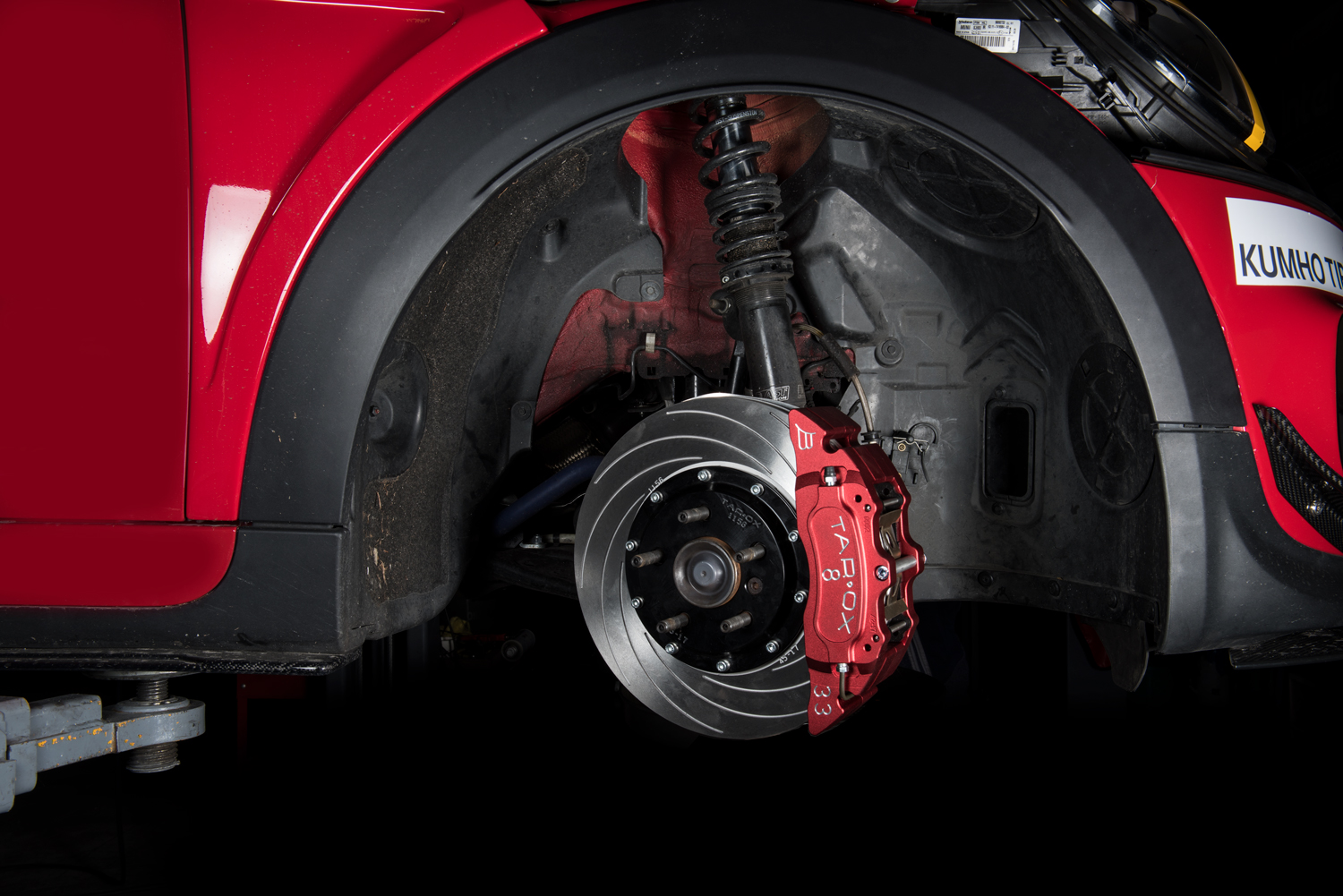
TAROX Brake Kit Fitting Guide
- Online version of fitting guide supplied with all TAROX brake kits – please email info@tarox.com if hard copy is required
- Installation of any component or system should only be performed by persons experienced in the installation and proper operation of disc brake systems. A TAROX brake kit will not function as intended and may even cause damage if misused or if not installed properly to the correct specifications.
- It is the responsibility of the individual installing a TAROX brake kit to determine its suitability for that particular application. It is the ultimate seller’s responsibility to ensure that the sale of the TAROX brake kit is compliant with all applicable laws and regulations.
- Each TAROX brake kit was designed, engineered and tested for a specific make and model of vehicle; in case of sale of the vehicle it should not be removed to be adapted to a different make and model or sold for a different application.
PRELIMINARY CHECK OF THE STATE OF THE CAR
A- SUSPENSION
Compared to the more common sliding calipers, the opposed piston calipers featured in all TAROX brake kits transmit more vibrations of all types to the brake pedal and/or to the steering wheel. As a consequence, and in particular on second-hand vehicles, bearings, all parts of the suspension, bushes, heads, axles shaft must be checked in accordance with the vehicle manufacturers manual and, if necessary, replace before installing a TAROX brake kit. If the worn parts are not checked and replaced, the discs could be permanently damaged, with consequent reduction in performance and vibration on the steering wheel and/or on the brake pedal even after only a few kilometres after installation.
B -WHEEL FITMENT
Although TAROX brake kits usually fit standard OE wheels, before installing it is strongly recommended to check a wheel for clearance by means of the wheel clearance template which can be requested at TAROX. If use of a wheel spacer cannot be avoided to obtain wheel clearance, then it is important to only consider use of hub centric spacers, supplied by reputable manufacturers.
PRELIMINARY INFORMATION ON TAROX BRAKE COMPONENTS
A -DISC ORIENTATION
The orientation of the discs is the following
F2000 https://www.youtube.com/watch?v=XBJS6WAVInM
Sport Japan https://www.youtube.com/watch?v=8y54x1YFLmY
B – CALIPER ORIENTATION
TAROX calipers are directional: in some models a small arrow denotes the direction of disc rotation, in any case when mounted on the vehicle, the bleed screw must be ALWAYS at the top of the caliper.
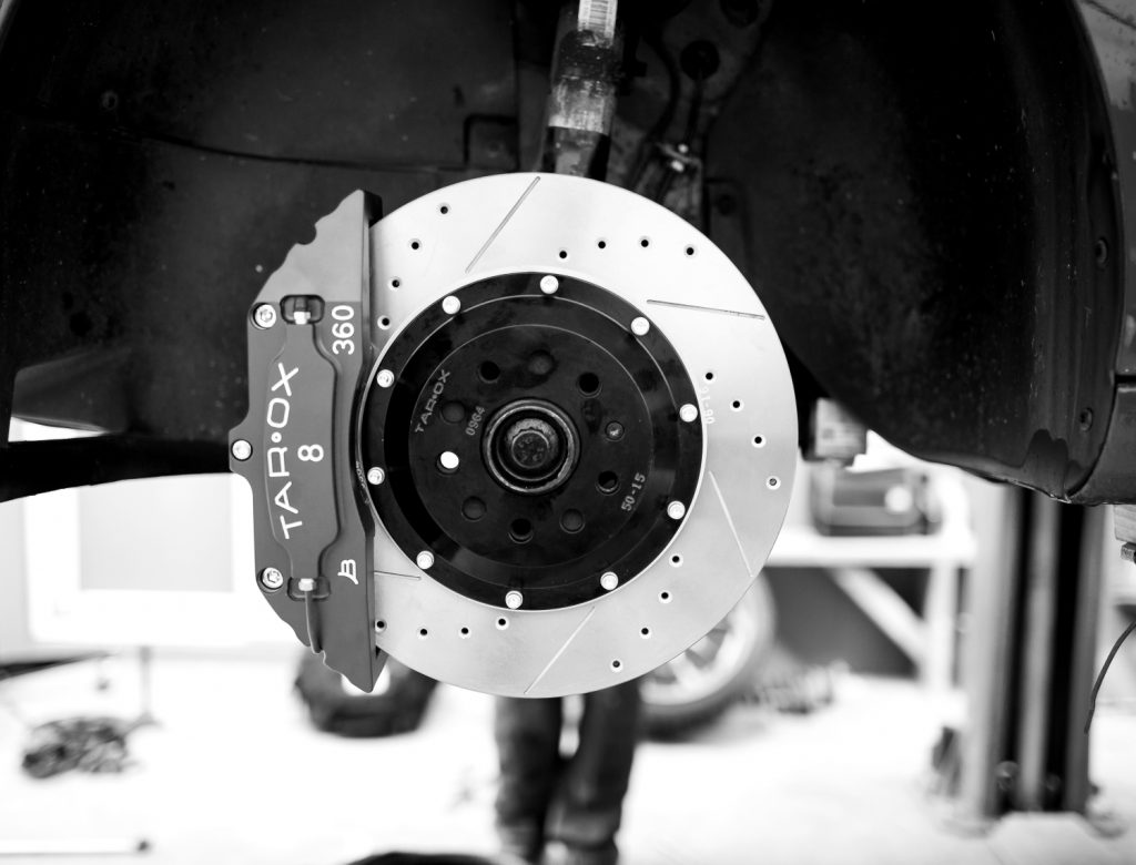
C- DISC AND BELL SUB-ASSEMBLIES
- Most TAROX brake kits features a disc and bell. The mounting system of the disc to the bell is specifically designed for this type of application. Unless on occasion of replacing a worn out disc, under no circumstances, should the bolts holding the disc to the bell be either loosened or tightened from their factory settings.
- When disc require replacement, it is recommended that the alloy bell is checked too and if worn out, to replace it.
- When replacing only the discs, it is recommended to resurface the discs with the existing bell to guarantee the that the discs and bell sub assembly is perfectly level
- Always replace discs in pairs.
D -BRAKE PADS
The brake pads that are provided with TAROX Upgrade Kits are meant to deliver effective performance when used at cold temperatures as well as higher temperatures seen during performance driving. If you are interested in using alternative friction materials, please contact TAROX Technical Department for recommendations.
WARNING: the brake pads supplied with TAROX Upgrade Kits do not have wear sensors. Pads must be inspected periodically- at least every 5000km and always after a session on track – to ensure that disc damage and brake impairment does not result due to overly worn pads. Pads are considered fully worn when the friction material reaches 2mm (0.08”) in thickness.
DANGER! Using the TAROX Brake Upgrade with worn out pads causes permanent damages to the discs and to the piston O-rings
PRACTICAL INFORMATION: BYPASS OR REMOVAL OF THE BRAKE PAD WEAR SENSOR
This procedure is only applicable to those vehicles equipped with an electronic pad wear indicator.
If your car is fitted with a brake pad wear indicator it may not be compatible with your TAROX brake kit. Having a brake pad wear indicator is not a necessary requirement and its removal will in no way hinder the performance of your TAROX brake kit. However the removal of indicators in some instances can cause a light to appear on the dashboard: in this case it is possible to create a loop in the circuit to turn this light off. TAROX recommend that any work should be carried out by a qualified professional.
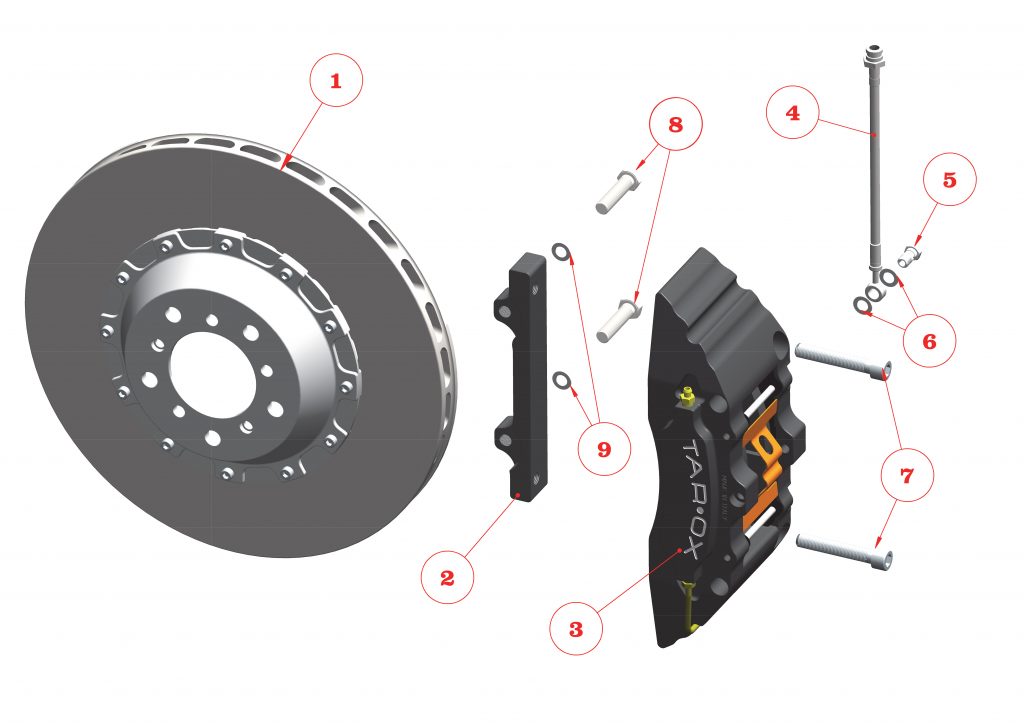
TAROX UPGRADE KIT COMPONENT LIST.
The following is a list of components which are included in TAROX brake kit boxes, and include all components for both corners of the vehicle.
2 x Multi -pistons Caliper including brake pads
2 x Disc and bell assembly / one piece disc
2 x Adapting brackets
2 x Brake hose assembly including copper gaskets (4)
6 x Shim washer 12
EQUIPMENT REQUIREMENT.
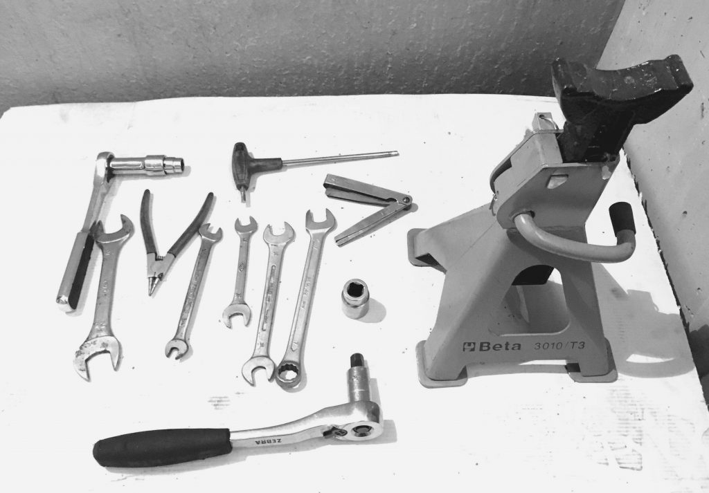
The following tools and equipment are necessary for the installation of TAROX Upgrade Kits:
– Combination spanners, torque wrench with sockets and socket head cap screw drive bits
– Pliers and hose clamps
– Screwdriver
– Brake fluid
– Jack and axle stands
– Clean cloths including emery cloth
– Solvent for cleaning
– Vehicle service manual
– Socket set and Cap screw socket set
– Wire brush
ORIGINAL COMPONENT REMOVAL
It is assumed that the operations starts with the car safely raised and supported in a safe and appropriate environment and the wheel removed.
Step 1 – Attach bleed bottle to the bleed screws on both sides of the vehicle and then release the bleed screws. This helps prevent fluid loss from hydraulic fittings, when they are loosened. Thoroughly clean the areas around the hydraulic hoses ensuring that all dirt and debris has been removed.
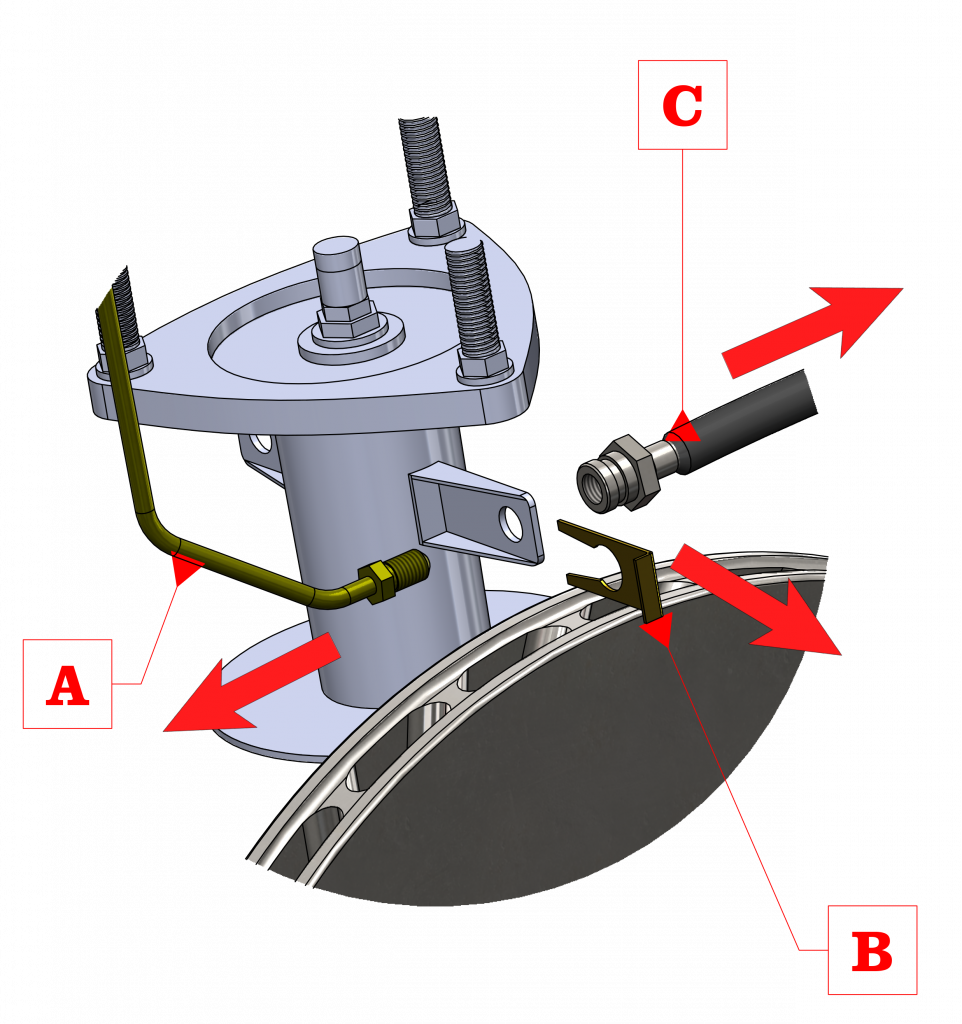
Step 2 – Using a brake line ring spanner or line-wrench loosen the brake line fitting at the chassis end. Have a clean cloth and drain pan available to catch any brake fluid which leaks out. If present, carefully remove all retaining clips from the flexible brake line hose. Avoid damaging or loosening the clips – if any – as these may be required for the new hydraulic line.
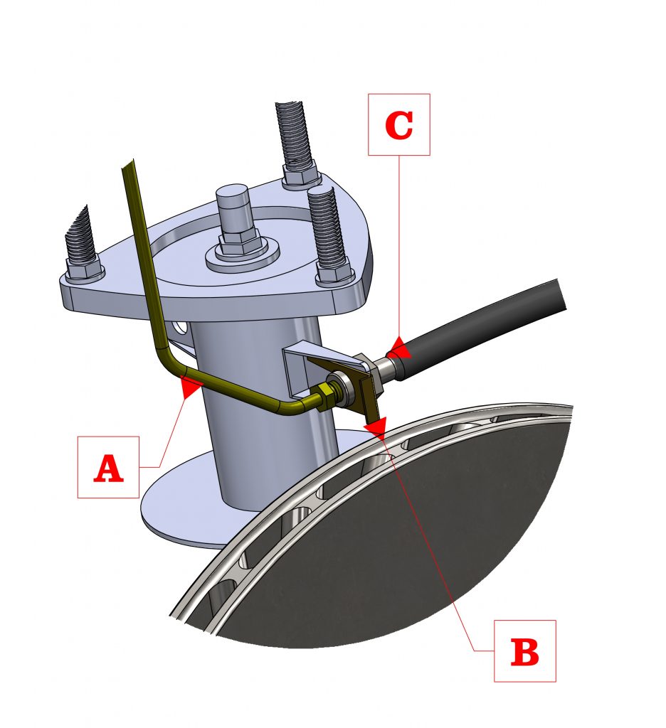
Step 3 – Remove the flexible brake line hose from the chassis bracket, and any other in-Iine connections that it may have. The flexible brake line hose may remain connected to the brake caliper. It is advisable to plug this to prevent dirt ingress and leakage during storage/disposal.
CAUTION!
Avoid any contact between the brake fluid and any painted surface. Should this happen, wash immediately the surface in question with soaped water to prevent damages to the paintwork.
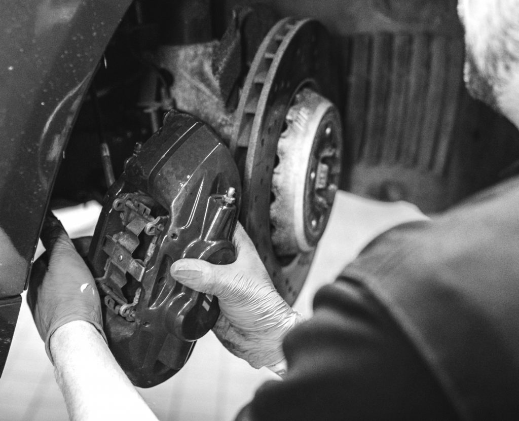
Step 4 – Remove the original caliper mounting bolts fastening the caliper to the knuckle. Remove the caliper-hose assembly.
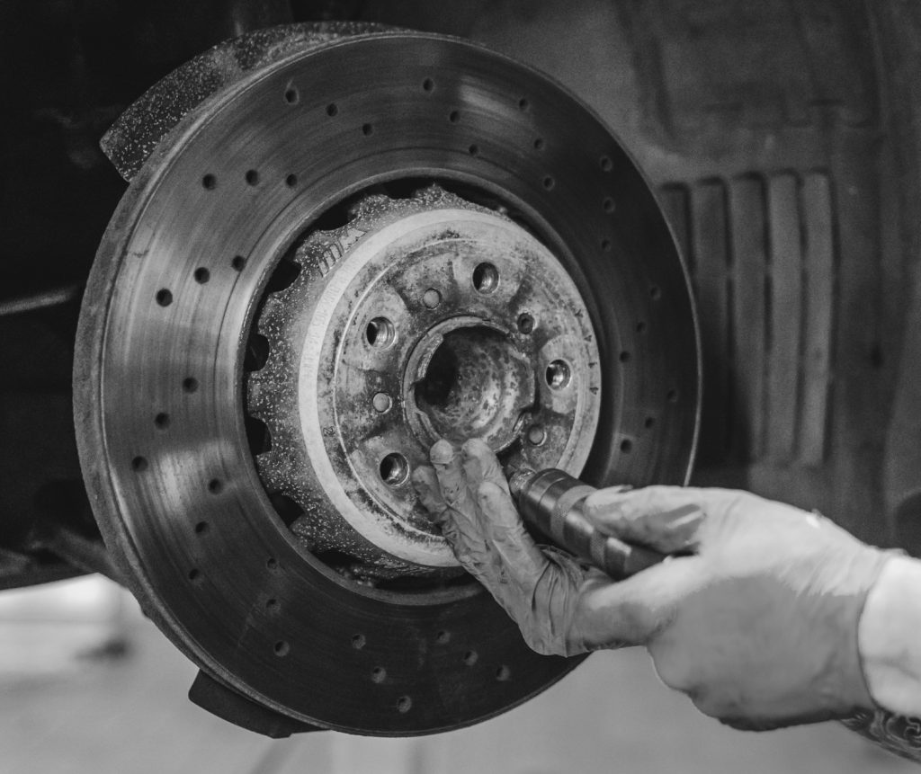
Step 5 – Locate and remove any screws or bolts holding the original brake disc to the hub. Remove the original disc from the hub. If the disc is difficult to remove use a rubber mallet to tap the back side of the disc at several points equidistant around its circumference until it is freed from the hub face. The disc should then be removed.
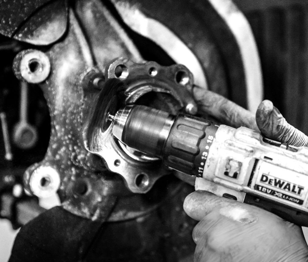
Step 6 – The mounting surface of the bracket must be in full contact with the mating surface on the knuckle, there must not be any interference between the bracket and the knuckle. To that end, carefully clean the bracket mounting surfaces using a cloth moistened with solvent to remove any contaminants and then medium emery paper. If corrosion is present on these surfaces, remove with an abrasive pad or wire brush. Ensure no corrosion remains and that there are no burrs on these surfaces.
Note: that the TAROX mounting bracket may use the opposite face of the mounting lug on the upright instead of the standard location. In this case, ensure there are no burrs or corrosion on these faces by following the cleaning processes described above.
Regardless of which bolts are used, torque to the vehicle manufacturer’s specification for bracket to suspension mounting.
Step 7- Thoroughly clean the disc mounting area of the hub face using a cloth moistened with solvent to remove any contaminants. If corrosion is present on these surfaces, remove with an abrasive pad or wire brush. Ensure the mounting area is free of corrosion and burrs.
TAROX BRAKE KIT COMPONENT INSTALLATION
Step 8 – After having thoroughly cleaned the bracket mounting point, offer up the new mounting bracket to the hub, ensure correct fitment – the TAROX logo MUST be facing the engine – then bolt the bracket to the original caliper mounting.
Note that the TAROX mounting bracket may use the opposite face of the mounting lug on the upright instead of the standard location. In this case, ensure there are no burrs or corrosion on these faces by following the cleaning processes. It is strongly recommended to tighten fully only when satisfied that no further adjustment is required.

Step 9 – The TAROX brake kit discs are ready to be installed: they must not be treated with any kind of lubricant or protectant. Offer up the discs to the hub. If the disc does not sit flat on the hub face and rotate freely with a minimum of 3mm .(1/8”) of clearance, then the shield/guard must be removed or bent away from the disc to achieve the 3mm clearance.
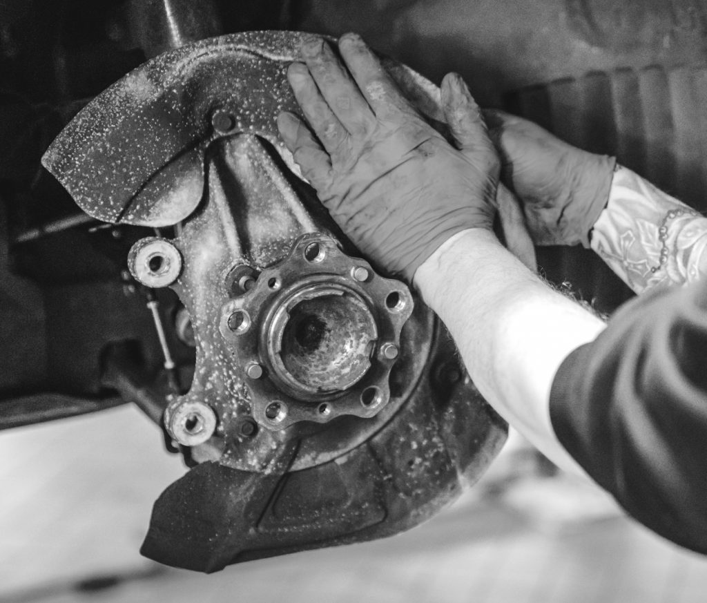
Refer to the vehicle manufacturer’s service manual for the removal procedure. Ensure the discs rotate without run out; if necessary further clean the disc mounting area.
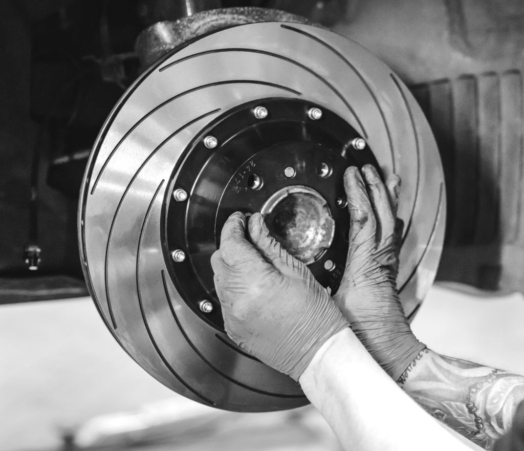
Step 10 – With the disc and bell assembly/one piece disc still in position and secured on the hub flange guide the new caliper assembly over the disc and bolt the caliper to the caliper mounting bracket using the caliper socket cap head fixing bolts supplied. Do not tighten the bolts.
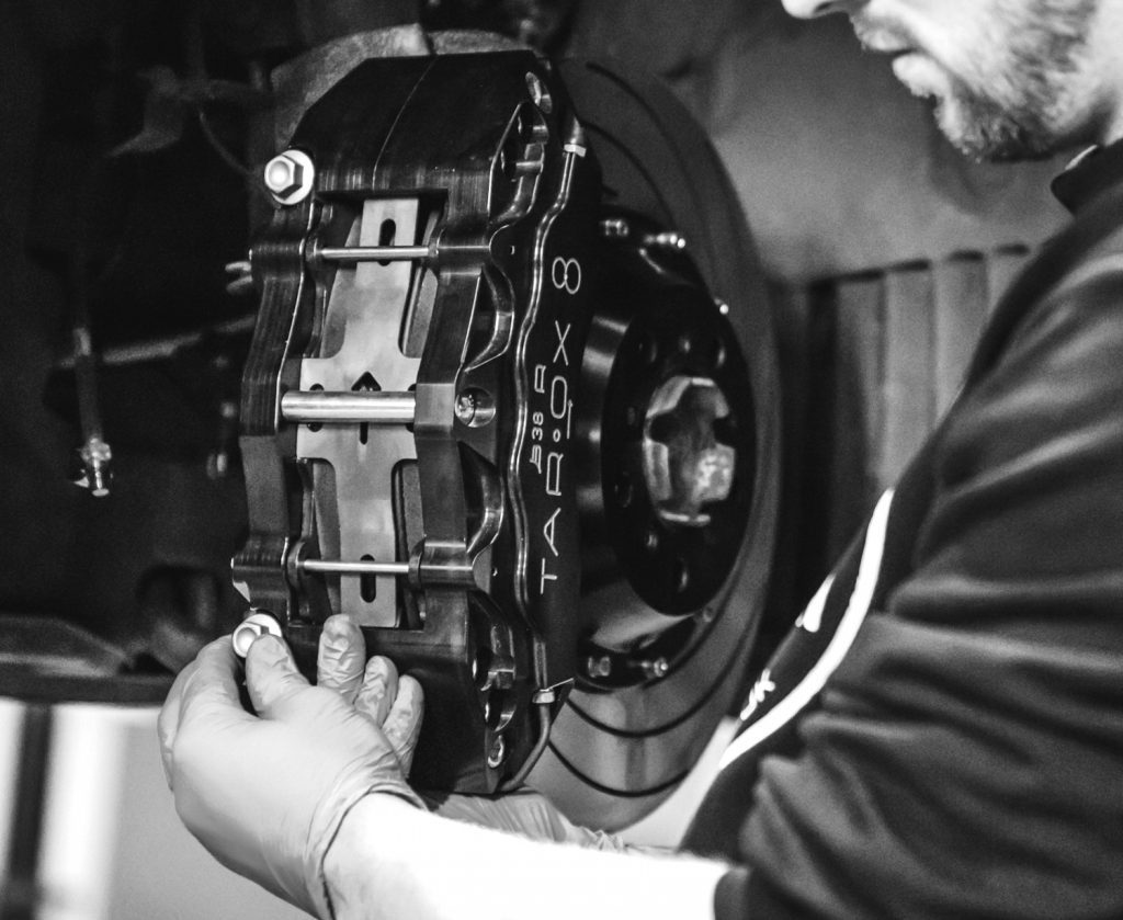
Step 11 – Check that the caliper disc pathway has a minimum of 1mm (0.04”) of clearance to each disc face. If unequal spacing is measured, remove the caliper, disc and bracket. Add 0.5mm (0.02”) shim washers to centralise the caliper noting that the spacer thickness is half of the difference between the measured gaps. For example, if gaps of 2mm (0.08”) and 1mm (0.04”) are measured, just 1 shim washer of 0.5mm (0.02”) needs to be used.
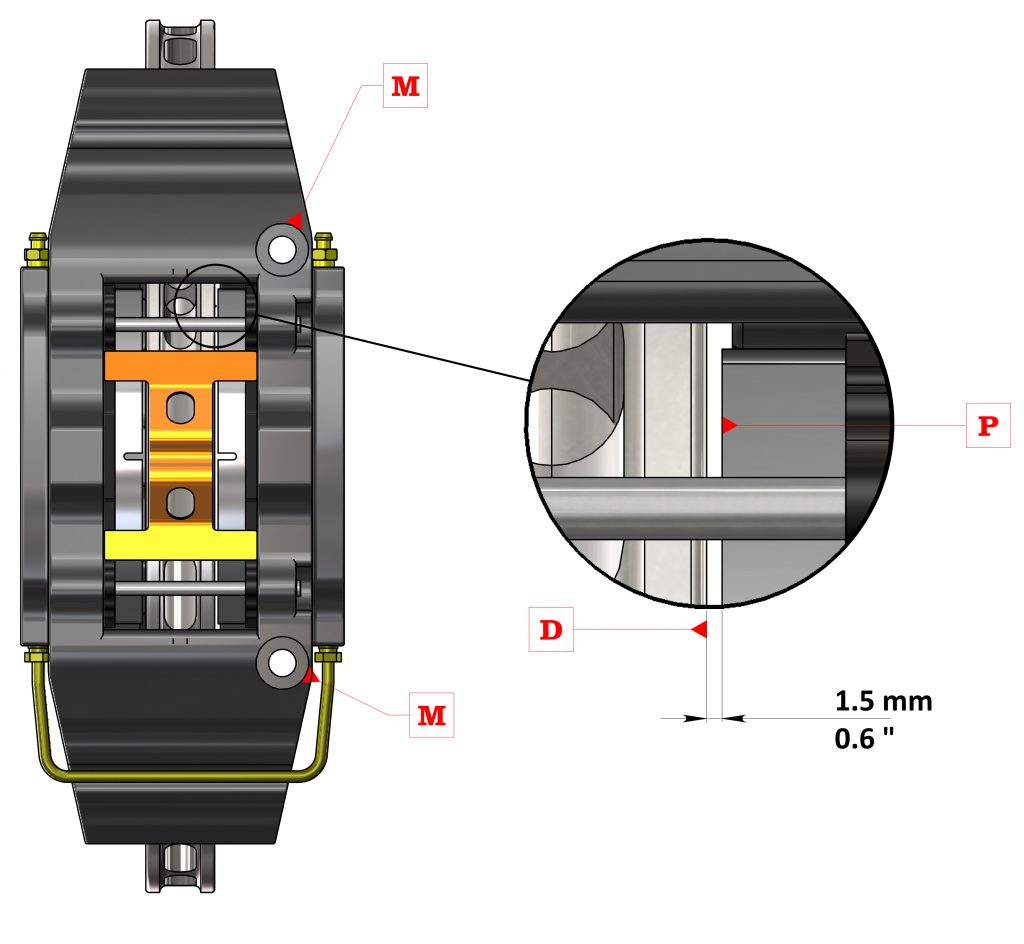
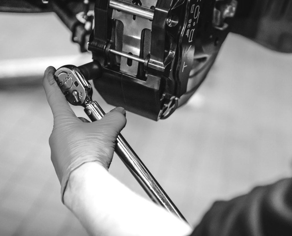
Step 12– Refit all the components ensuring the disc is re-installed in the correct position and check the disc clearance again. Once the correct spacing has been achieved, tighten the bolts applying the torque specified in Appendix 1 – Bottom of post.
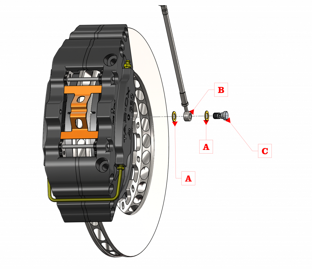
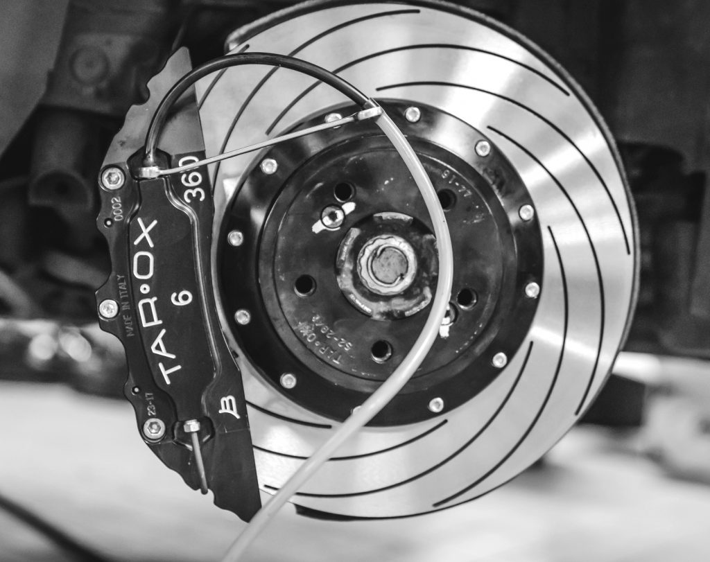
Step 13 – Insert a copper washer on the banjo bolt, then the banjo fitting and then another copper washer. Thread the bolt into the fluid inlet of the caliper 1 and only tighten loosely by hand, so that the fitting can rotate during the next steps.
Step 14 – Thread the caliper end of the brake hose onto the inlet adapter fitting, leaving loose, so that fitting can be correctly oriented during the following steps.
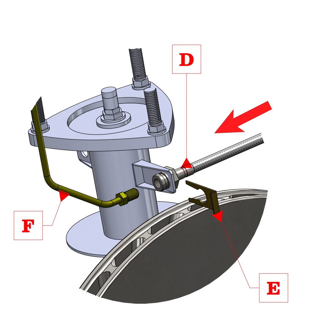
Step 15– Reconnect the brake hose to the fluid supply system on the chassis. Fit any fastening clips. Tighten the fitting to the torque prescribed by the vehicle manufacturer. Tighten the end of the banjo fitting to the caliper finger tight. Ensure that the hose does not become twisted.
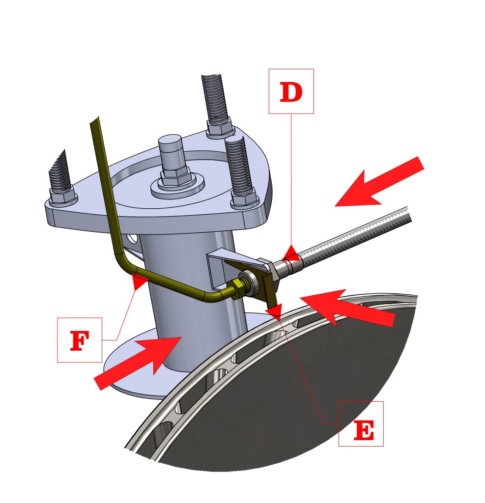
Step 16– Temporarily install the wheel, move the steering through its full range of motion and inspect the general brake line installation to ensure that it does not kink, stretch, or unnecessarily come in contact with suspension, transmission, wheel or chassis components. The brake hose path may be altered in order to achieve the best fitment under all conditions.
DANGER!
Incorrect positioning of the brake hose can cause its damage leading to leakage of the brake fluid and malfunctioning of the braking system with consequent danger of death, serious injury or property damage to others
Step 17– Tighten the banjo bolt , to a torque of 25Nm (18lbs-ft).
Step 18– Repeat these operations for the other side of the vehicle.
Step 19- Bleed the brakes making sure that there is no air in the system. TAROX recommends using its RoadRace brake fluid.
WARNING
- NEVER EVER empty the brake fluid reservoir
- ALWAYS use brake fluid from fresh bottle
- Avoid brake fluid contact with any paint work
- Tighten the bleed screws to the recommended torque of 17Nm (12.5lbs-ft). Clean the area with a cloth and solvent.
FINAL CHECKS
- Inspect for any fluid leaks while system is under pressure. Wipe clean any spilled fluid. Carefully clean around all hose fittings, unions and joints. Check for fluid leaks again whilst the system is under pressure.
- Check the fluid level in the brake fluid reservoir. Fill to the maximum level indicated on the reservoir.
- Confirm that all the hoses are in their correct positions and secure.
- Reinstall the wheels and torque the wheel nuts to the vehicle manufacturer’s specification. Spin the wheel slowly and listen to see if there is any rubbing sound – for instance, a splash plate fouling the rear disc face.
- Check the wheel on full lock to lock and on full drop to ensure the brake hoses have adequate free play and do not foul wheel rims.
- Carefully lower the vehicle in compliance with safety standards. Again check the hose clearances from lock to lock.
BEDDING NEW PADS AND DISCS
The purpose of this procedure is to gradually increase the temperature in the components without causing thermal shock, and to mate the brake pad and disc friction surfaces. This is how it should be done;
- While vehicle is stationary, pump brakes to ensure a firm pedal.
- Drive vehicle cautiously to test fit and function: brakes should be smooth, with no vibrations or judder, etc.
- For the first 20 km (12miles), light braking from 80-100km/h (50/60mph) down to 50km/h (30mph), if possible repeating the operation 8 times.
- Do not attempt any high-speed stops down to zero as only the faces will heat up with the mass remaining cool along with the mounting area.
- For the next 150 km (100 miles) increase the braking pressures similar to stopping in traffic, again avoiding if possible full stops from above 110 km/h (70mph). By now the area around the mounting bolts should be a light blue temper colour. This is a good indication that the correct heat soak has been achieved.
- For the next 150 km (100 miles) gradually increase the braking effort after this full power stops can be used. The disc should now be an even dark to light blue temper colour, depending on the pad type and the braking effort being used during the process. This procedure must be completed before any track / circuit use
The system is now ready for normal use.
TRACK DAY EVENTS
If used at a Track day the following points must be adhered to prevent typical causes of vibration such as brake pad transfer, DTV – Disc Thickness Variation – and thermal shock
- At the start of a session, perform at least one warming up lap for the brakes by gradually increasing the effort at each corner and not dragging the brakes under power left foot braking.
- Perform at least one cooling down lap at the end of the session using minimal braking.
- Do not leave your foot on the brake when parked in the paddock after a track session. If you do, the hot spot created by the pad can distort the disc in that localized area causing a high spot, resulting in vibration under braking.
- Check your brake system thoroughly after each track event.
- On the majority of car installations race circuit use can be more exacting on the brake system than a fully prepared race car due to the following: a) none or minimal cooling, b) increased chassis weight,c) longer braking distances due to driving technique or tyre grip. Therefore it is very important to check your brake system thoroughly after such use, bearing in mind race cars on average cover less than 50 laps of a Track/Circuit before being serviced.
MAINTENANCE
- Unless explicitly indicated, the system does not require and particular maintenance. Wear on disc should be monitored, checking that the thickness does not drop below the minimum specified.
- TAROX recommends a maximum brake disc wear of 1.5mm from new brake disc thickness.
APPENDIX 1
| BRAKE KIT TORQUE SETTINGS | |||||
| Nm | lb/ft | ||||
| Bell to rotor (M6 8.8) | 11 | Mozzo/disco (M6 8.8) | |||
| Bell to rotor (M6 12.6) | 18 | Mozzo/disco (M6 12.6) | |||
| Bell to rotor (M8) | 22 | 16.2 | Mozzo/disco (M8) | ||
| Caliper to bracket (M12) | 70 | 51.6 | Pinza/Staffa (M12) | ||
| Bracket to vehicle hub: | Staffa/Montante | ||||
| Threaded bracket (M12) | 70 | 51.6 | Staffa filettata (M12) | ||
| Threaded bracket (M14) | 180 | 132.8 | Staffa filettata (M14) | ||
| Threaded hub (M12) | 90 | 66.4 | Montante filettato (M12) | ||
| Threaded hub (M14) | 240 | 177.0 | Montante filettato (M14) | ||
| Banjo | 21 | 15.5 | Raccordo a occhiello | ||
| Bleed nipple (max) | 21 | 15.5 | Vite di spurgo | ||
| * All settings apply to dry threads on a cold brake system | |||||
Previous article« TAROX @ Players Classic – Goodwood England.
Next articleStopping with style: Scott’s Corrado 20VT »

